WPWED Series Double Stage Worm Gearbox

The WPWED Series is an EVER-POWER double stage worm gearbox manufactured in Hangzhou and supplied factory-direct from Singapore. Gear ratios 1:200 – 1:900, max output torque 9,066 N·m, efficiency 40-60%. Input: IEC hollow bore. Output: Solid shaft. Mounting: Universal – multi-position. Centre distance 40-175 mm. 20CrMnTi worm hardened to HRC 58-62. ISO 9001:2015 and CE certified. MOQ 10 pcs. Sample in 15-25 days. 24 h quote response.

WPWED Series Double Stage Worm Gearbox
ISO 9001:2015
CE

Input
IEC hollow bore
B5 / B14 motor flange

Output
Solid shaft
Orizzontale

Rapporto
1:200 – 1:900
Double stage

Max Torque
9,066 N·m
Size 135–135

Mounting
Universal – multi-position
40–175 mm

⚙
1:200 – 1:900
Gear Ratio
⚡
40–60%
Efficienza
🔩
9,066 N·m
Max Output Torque
🛡
HRC 58–62
Gear Hardness
📐
40–175 mm
Centre Distance

01
Product Overview
WPWED Series Double Stage Worm Gearbox — Technical Overview

The WPWED Series Double Stage Worm Gearbox pairs IEC hollow bore motor input with the universal multi-position D-type housing and two-stage reduction (1:200–1:900). The split D-type housing can be face-mounted in multiple orientations, giving maximum flexibility for high-ratio direct-motor-coupled drives in non-standard installation geometries.

Split D-type HT250 cast iron housing for multi-position IEC motor mounting. Two 20CrMnTi worm shafts at HRC 58–62, ZCuSn10Pb1 bronze wheels. Efficiency 40–60%. Oil fill confirmed per orientation.

Factory-direct from Singapore. View the double stage range or request a quotation.

WPWED worm gear reducer internal structure and component diagram

WP Series Worm Gear Reducer — Internal Structure and Main Components

02
Shaft Direction
WPWED Series — Input and Output Shaft Orientations
Multiple shaft direction positions are available. Specify the position code when ordering. Oil fill volume changes with non-standard orientations — EVER-POWER confirms the required adjustment.

WPWED worm gear reducer shaft direction diagram — input and output shaft orientation positions

WPWED Series — Shaft Direction Diagram · A: input below · S: input above · O: output upward · X: output downward · T: input upward · V: input downward

Code Input Shaft Position Output Shaft Position Typical Use
UN Horizontal — below centre (standard) Orizzontale Horizontal conveyor drives, standard floor-mounted machines
S Horizontal — above centre Orizzontale Overhead mounting, inverted or top-fed drives
O Orizzontale Vertical — upward Lifting columns, vertical screw drives, hoist applications
X Orizzontale Vertical — downward Gravity-assisted feed, downward discharge drives
T Vertical — upward Orizzontale Vertical input from above, tower or mast drives
V Vertical — downward Orizzontale Floor-level motor with downward vertical input shaft
ℹ IEC Input + Universal Mount + Double Stage — WPWED Series
The WPWED combines the most installation flexibility (universal D-type housing), direct IEC motor coupling, and very high two-stage ratios. This is the preferred choice when drive orientation is unknown at procurement time and a high-ratio IEC-coupled drive is required.

03
Dimensional Drawing
WPWED Series — Overall Dimensions and Mounting Geometry
Full dimensional data covering 40–175 mm centre distance range. 2D DXF and PDF drawings available within 24 hours at no charge.

WPWED worm gear reducer dimensional drawing — overall dimensions mounting hole pattern and shaft sizes

WPWED Series — Structural Dimensional Drawing · All dimensions in mm · Sizes 40–175 mm · DXF and PDF on request within 24 hours

Dimension Symbol Reference
A / AB Overall length / length excluding shaft extension B / BB Overall height / base plate height
CC Output shaft centreline height above base HS / U Input shaft diameter / usable shaft length
T x V Input shaft key width x key depth LS / S Output shaft usable length / diameter
W x Y Output shaft key width x key depth E / F / G / M / N Foot mounting hole positions and pitch

04
Specifiche tecniche
WPWED Series — Full Parameter Table
Input speed: 1,500 r/min · Housing: HT250 cast iron · Seal: NAK / SKF · Lubricant: ISO VG220 · MOQ: 10 pcs · Port: Shanghai / Ningbo

WPWED worm gear reducer specification table — input power and output torque for all sizes and ratios (brochure p.18)

WPWED Series — Parameter Table (brochure p.18) · Columns: Size · Ratio · A/AB/B/BB/CC/H/HL/M/N/E/F/G/Z · Input shaft HS/U/T×V · Output shaft LS/S/W×Y · Weight (kg) · Oil (L)

Dimensione Rapporto Max Input (kW) Max Output Torque Weight (kg) Oil (L)
WPWED Series · Split cast iron (D-type) · Universal – multi-position · 20CrMnTi Worm · ZCuSn10Pb1 Bronze Wheel · Input: 1,500 r/min
40–40 1/200–1/900 0.37

84 N·m

16 0.30
60–60 1/200–1/900 0.93

303 N·m

35 0.99
80–80 1/200–1/900 2.62

819 N·m

81 2.95
100–100 1/200–1/900 5.51

2,745 N·m

169 6.40
120–120 1/200–1/900 11.00

5,290 N·m

344 13.60
135–135 1/200–1/900 14.00

9,066 N·m

454 18.00

* Peak output torque at the highest-torque ratio per size · Full ratio-by-ratio data available — request the complete data sheet

05
Material and Construction
Engineering Specifications — WPWED Series

Worm Shaft
Primary drive element
Alloy grade20CrMnTi
Surface hardnessHRC 58–62
Heat treatmentCase carburising + quenching
Surface finishGround, Ra ≤ 0.8 μm
Shaft core40Cr steel

Worm Wheel
Output driven element
Alloy gradeZCuSn10Pb1 tin-bronze
Tooth formZI involute profile
Bearing brandSKF / C&U / HRB
Shaft sealNAK / SKF lip seal
Leak test2.5 bar · 100% of units

Housing and Assembly
Structure and sealing
Housing gradeHT250 grey cast iron
Housing formSplit cast iron (D-type)
LubrificanteISO VG220 gear oil
InputIEC hollow bore
OutputSolid shaft

06
Selection Correction Factors
Power Calculation and Correction Coefficient Tables
Apply correction factors a₁ and a₂ to the rated torque before selecting a gearbox size. Use Table 3 to verify motor input power.

Table 1
Ambient Temperature Correction Coefficient a₁
Ambient Temperature (°C) 10 – 25 26 – 30 31 – 40 41 – 50
a₁ 1.0 1.1 1.0 1.6

Table 2
Duty Condition Correction Coefficient a₂
Operating Condition Daily Running Hours (h)
≤ 2 h > 2 – 10 h > 10 – 24 h
Smooth running 0.8 1.0 1.2
Moderate shock load 1.0 1.2 1.4
Heavy shock load 1.25 1.5 1.75
ℹ If the gearbox starts, reverses, or changes direction 12 or more times per hour during operation, multiply the table value by an additional factor of 1.2.

Table 3
Input Shaft Power Calculation and Efficiency Coefficient u
Input Power Formula
P = T × n₂ ÷ (9550 × u)
P — Input shaft power (kW)
T — Corrected torque value (N·m)
n₂ — Output shaft speed (r/min)
u — Transmission efficiency (from table below)

Rapporto 1:10 1:15 1:20 1:25 1:30 1:40 1:50 1:60
Efficiency u 0.76–0.90 0.75–0.86 0.74–0.84 0.72–0.82 0.68–0.70 0.65–0.75 0.62–0.72 0.60–0.70

07
Lubrificazione
Recommended Lubricants by Speed and Temperature
Select oil grade based on worm shaft speed and mounting orientation. Change after the first 100 operating hours, then every 2,500 hours.

Oil Grade Selection by Worm Shaft Speed and Operating Position
Worm Shaft Speed (r/min) Oil Type Upper Worm / Vertical Lower Output Shaft Vertical
Over Up to
1,000 3,000 Synthetic oils PG460 PG220
— 1,000 PG460
2,000 3,000 Mineral oils ISO VG460 ISO VG200
750 2,000 ISO VG320
250 750 ISO VG460
— 250 Mineral oils ISO VG660 ISO VG660

International Brand Equivalents by Ambient Temperature
Ambient Temp. Oil Type Esso Texaco Mobil Shell AGMA
15–60°C
−9 to −16°C
Mineral oils Spartan EP220 Regal Oil R&D 320 DTE LIL BB Shell Omala Oil 220 5
Compounded oils Sparan EP320 631-Honor Cylinder Oil Mobil 600W Cylinder Oil Shell Omala Oil 320 7
Extreme pressure Spartan EP460 Meropa 460 Mobil Gears 634 Shell Omala Oil 460 7EP
50–125°C
10–52°C
Mineral oils Spartan EP320 Regal Oil 320 DTE OIL AA Shell Omala Oil 320 6
Compounded oils Spartan EP460 642-650T Cylinder Oil Mobil 600W Super Cylinder Oil Shell Omala Oil 460 8
Extreme pressure Spartan EP680 Meropa 680 Mobil Gears 636 Shell Omala Oil 660 8EP
ℹ Drain and flush the unit after the first 100 operating hours. Thereafter, change oil every 2,500 hours or 12 months, whichever comes first. Use synthetic oil for continuous 24-hour duty.

08
Diagnosi dei guasti
Troubleshooting Guide — Common Faults and Remedies
Identify the fault symptom, locate the probable cause, and apply the recommended corrective action before returning the unit to service.

Fault Symptom Probable Cause Recommended Action
Overheating Motor, gearbox, or driven machine misaligned at coupling Re-align all three shafts to be co-axial. Check coupling and re-torque fasteners.
Overload running Reduce load to within rated torque. Apply correction factors a₁ and a₂.
Lip seal worn or excessively tight Apply grease at the seal lips; replace seal if worn.
Incorrect oil level or degraded lubricant Top up or drain and refill to the correct level. Use the grade specified in Table 4.
Vibrazione Motor, gearbox, or driven machine poorly fixed or misaligned Inspect and re-tighten all mounting fasteners. Re-align coupling.
Worm wheel tooth surface worn or damaged Replace the worm wheel assembly.
Bearing worn Replace bearing. Check shaft for scoring before refitting.
Abnormal Noise Bearing worn or clearance too large Replace bearing and adjust preload.
Poor worm wheel tooth mesh Check and adjust tooth contact; replace worm wheel pair if necessary.
Insufficient lubricant Top up oil to the correct level.
Foreign matter in housing Drain oil completely, flush housing, remove debris, refill with fresh oil.
Oil Leakage Lip seal damaged Replace lip seal.
Shaft journal surface worn at seal contact Replace input or output shaft. Fit new seal to match.
Oil overfilled Drain to the correct level per the oil gauge indicator.
Drain plug loose or oil gauge cracked Re-seal and tighten drain plug. Replace oil gauge if cracked.
Rapid Worm Wheel Wear Overload running Reduce load; check application duty factors against rated capacity.
Wrong lubricant grade Drain and refill with the correct grade from Table 4.
Insufficient lubricant Top up to the correct level at the oil gauge.
Oil change interval exceeded; lubricant degraded Drain, flush, and refill per the maintenance schedule.
Operating temperature too high Resolve overheating fault first (see above), then reduce ambient temperature or improve ventilation.

06
Applicazioni
WPWED Series — Industry Use Cases

EVER-POWER worm gearbox manufacturing facility Hangzhou — CNC gear hobbing and precision assembly

EVER-POWER Manufacturing
CNC gear hobbing, heat treatment, and 100% pressure-testing in Hangzhou. Every WPWED unit is inspected and pre-filled before dispatch.

WPWED worm gear reducer installed in industrial drive application

WPWED Series in Service
The WPWED worm gear reducer serves conveyor, mixer, packaging, and agricultural drives across 40–175 mm centre distance.

🔄
Flexible-Layout IEC-Coupled High-Ratio Drives

WPWED 80–175
Any orientation + IEC + high ratio

High-ratio drives in machine designs where the final drive orientation is not fixed at the time of gearbox selection, and direct IEC motor coupling is required.

🏭
Non-Standard Orientation Reactor Drives

WPWED 100–175
Up to 9,066 N·m

Agitator and mixer drives in reactors with unusual geometry, where the WPWED multi-position housing avoids the need to order a specific orientation variant.

🚧
High-Ratio Conveyor with Flexible Install

WPWED 60–135
Multi-position compact

Very slow conveyor and indexing drives where the installation angle is determined by the plant layout rather than the gearbox catalogue.

⚙
General Industrial High-Ratio IEC Drives

WPWED 40–120
IEC direct + high ratio

General industrial high-ratio drives where a standard IEC motor must couple directly and the installation orientation is non-standard or varies across sites.

07
Produttore
EVER-POWER PTE. LTD. — Factory Direct from Singapore
Singapore-registered. Hangzhou manufacturing. No intermediaries — factory pricing and ISO-certified quality on every order.

EVER-POWER worm gearbox factory Hangzhou — production floor

EVER-POWER Production Base · Hangzhou, China · 3 Plants · CNC Gear Hobbing · Heat Treatment · 100% Pressure-Test

EVER-POWER PTE. LTD.
Singapore Registered · Hangzhou Manufacturing · 20+ Years Experience

ISO 9001:2015
CE Certified
Triple ISO

🏭
3 Plants
Manufacturing Facilities
CNC gear hobbing, case-hardening, assembly, and 100% pressure-test in Hangzhou.
🔬
HRC 58–62
Worm Shaft Hardness
Case carburising and quenching on every shaft. Ra ≤ 0.8 μm ground finish. Hardness verified by Rockwell test.
📦
MOQ 10 pcs
OEM from Small Batches
Custom ratios, shaft sizes, keyways. Sample 15–25 days; production 30–45 days.
🌎
50+ Countries
Global Export
EU · US · UK · AU · NL · BR · CA · KR. DDP and DAP available.
📋
Triple ISO
Certified Quality
ISO 9001:2015 · ISO 14001 · ISO 45001. CE marking on request.
⚡
24 h
Quote Response
Send size, ratio, quantity, application. Full quote + drawing within 24 hours.

FAQ
Frequently Asked Questions — WPWED Series Double Stage Worm Gearbox
How does the WPWED differ from the WPEDA?+
WPWED uses a universal multi-position D-type housing; WPEDA uses a standard D-type with fixed orientation. WPWED provides more mounting flexibility.
What IEC frames are compatible?+
Contact EVER-POWER with motor frame and shaft diameter.
Is the WPWED self-locking?+
Yes, strongly at these high ratios.
What is the MOQ and lead time?+
MOQ 10 pcs, 30–45 days. Samples 15–25 days.
Are drawings available?+
2D DXF/PDF within 24 hours.

Request a Quote — WPWED Series Double Stage Worm Gearbox
Provide your required centre distance (40–175 mm), gear ratio (1:200 – 1:900), shaft direction, mounting type, and quantity. Full quotation with dimensional drawing returned within 24 hours.

MOQ 10 pcs

Sample 15–25 days

Quote in 24 hours

DDP / DAP available

Request a Quote →
Email Us Directly

📞 +65 8866 2737 · Singapore

Riduttori ad ingranaggi

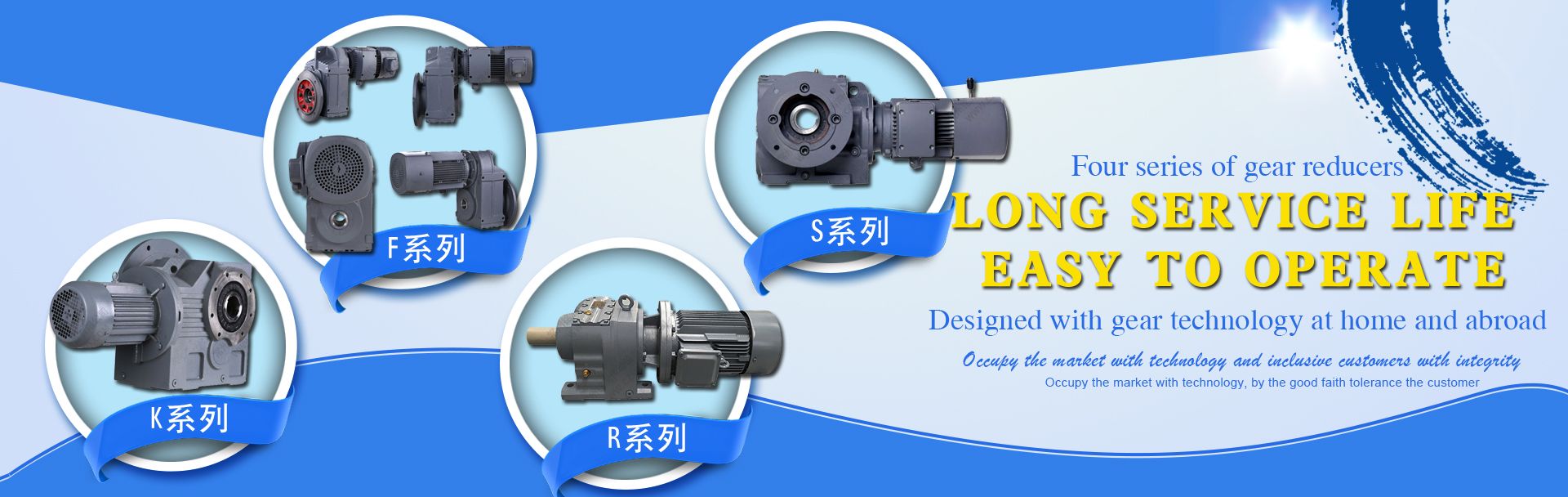
Capacità di produzione di ingranaggi di livello mondiale, fornitori di materiali di qualità e un processo di qualità all'avanguardia consentono a EPT di offrire il massimo livello di precisione, durata e resistenza. I riduttori epicicloidali EPT sono progettati e costruiti per applicazioni avanzate ad alta velocità e a gioco ridotto. I processi produttivi di EPT ci consentono di offrire eccezionali capacità di carico d'urto e varie opzioni di montaggio.
Trattamento della superficie

Ricottura, canonizzazione naturale, trattamento termico, lucidatura, nichelatura, cromatura, zincatura, passivazione gialla, passivazione oro, satinatura, verniciatura nera ecc.

Metodo di elaborazione

Lavorazione CNC, punzonatura, tornitura, fresatura, foratura, rettifica, brocciatura, saldatura e assemblaggio

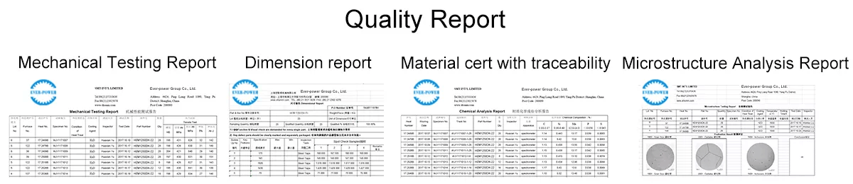
CQ e certificato

Tecnici autocontrollo in produzione, controllo finale prima del pacchetto da parte dell'ispettore di qualità professionale
ISO9001:2008, ISO14001:2001, ISO/TS 16949:2009

Pacchetto e tempi di consegna

Dimensioni: Disegni
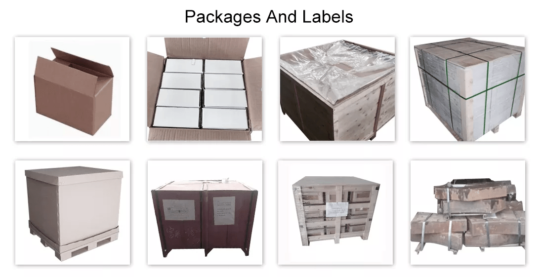
Cassa di legno/contenitore e pallet, o come da specifiche personalizzate.
15-25 giorni per i campioni. 30-45 giorni ordine ufficiale
Porto: porto di Shanghai/Ningbo
FAQ

D: Siete una società commerciale o un produttore?
R: Il nostro gruppo è composto da 3 fabbriche e 2 società di vendita all'estero.

D: Fornite campioni? È gratuito o extra?
R: Sì, possiamo offrire il campione gratuitamente, ma non paghiamo il costo del trasporto.

Q: Quanto tempo è il vostro tempo di consegna? Quali sono le vostre condizioni di pagamento?
R: In genere si tratta di 40-45 giorni. I tempi possono variare a seconda del prodotto e del livello di personalizzazione. Per i prodotti standard, il pagamento è: 30% T/T in anticipo, saldo prima della spedizione.

Q: Qual è il MOQ o il prezzo esatto per il vostro prodotto?
A: In qualità di azienda OEM, possiamo fornire e adattare i nostri prodotti a un'ampia gamma di esigenze. Pertanto, il MOQ e il prezzo possono variare notevolmente in base alle dimensioni, al materiale e alle ulteriori specifiche; ad esempio, i prodotti costosi o i prodotti standard avranno solitamente un MOQ inferiore. Vi preghiamo di contattarci con tutti i dettagli rilevanti per ottenere la quotazione più accurata.

it_ITIT