WPWKT Series Universal Worm Gearbox

The WPWKT Series is an EVER-POWER universal worm gearbox manufactured in Hangzhou and supplied factory-direct from Singapore. Gear ratios 1:5 – 1:60, max output torque 3,025 N·m, efficiency 60-82%. Input: Solid shaft. Output: Hollow bore shaft. Mounting: Universal – multi-position. Centre distance 40-250 mm. 20CrMnTi worm hardened to HRC 58-62. ISO 9001:2015 and CE certified. MOQ 10 pcs. Sample in 15-25 days. 24 h quote response.

WPWKT Series Universal Worm Gearbox
ISO 9001:2015
CE

Input
Solid shaft
Vertical — upward

Output
Hollow bore shaft
H7 tolerance

比率
1:5 – 1:60
Universal single stage

Max Torque
3,025 N·m
Size 250

Mounting
Universal – multi-position
40–250 mm

⚙
1:5 – 1:60
Gear Ratio
⚡
60–82%
效率
🔩
3,025 N·m
Max Output Torque
🛡
HRC 58–62
Gear Hardness
📐
40–250 mm
Centre Distance

01
Product Overview
WPWKT Series Universal Worm Gearbox — Technical Overview

这 WPWKT Series Universal Worm Gearbox provides a vertical upward input shaft and a hollow bore output shaft in the universal P-type housing. The motor mounts below the gearbox with its shaft pointing upward; the driven machine shaft engages the hollow bore directly without a coupling.

Vertical upward input shaft (T position), hollow bore output to H7 tolerance, integral P-type HT250 cast iron universal housing. 20CrMnTi worm shaft at HRC 58–62, ZCuSn10Pb1 bronze wheel, 60–82% efficiency. Oil fill adjusted for T orientation.

Factory-direct from Singapore. View the universal worm gearbox range or request a quotation.

WPWKT worm gear reducer internal structure and component diagram

WP Series Worm Gear Reducer — Internal Structure and Main Components

02
Shaft Direction
WPWKT Series — Input and Output Shaft Orientations
Multiple shaft direction positions are available. Specify the position code when ordering. Oil fill volume changes with non-standard orientations — EVER-POWER confirms the required adjustment.

WPWKT worm gear reducer shaft direction diagram — input and output shaft orientation positions

WPWKT Series — Shaft Direction Diagram · A: input below · S: input above · O: output upward · X: output downward · T: input upward · V: input downward

Code Input Shaft Position Output Shaft Position Typical Use
A Horizontal — below centre (standard) Horizontal Horizontal conveyor drives, standard floor-mounted machines
S Horizontal — above centre Horizontal Overhead mounting, inverted or top-fed drives
O Horizontal Vertical — upward Lifting columns, vertical screw drives, hoist applications
X Horizontal Vertical — downward Gravity-assisted feed, downward discharge drives
T Vertical — upward Horizontal Vertical input from above, tower or mast drives
V Vertical — downward Horizontal Floor-level motor with downward vertical input shaft
ℹ Vertical Upward Input + Hollow Bore Output — WPWKT Series
The WPWKT combines the T-position (vertical upward input) with hollow bore direct shaft output. The motor installs below the gearbox; the driven shaft engages the horizontal hollow bore from the side. Both the input coupling (motor to worm) and the output coupling (worm to driven shaft) are eliminated, minimising drive train component count.

03
Dimensional Drawing
WPWKT Series — Overall Dimensions and Mounting Geometry
Full dimensional data covering 40–250 mm centre distance range. 2D DXF and PDF drawings available within 24 hours at no charge.

WPWKT worm gear reducer dimensional drawing — overall dimensions mounting hole pattern and shaft sizes

WPWKT Series — Structural Dimensional Drawing · All dimensions in mm · Sizes 40–250 mm · DXF and PDF on request within 24 hours

Dimension Symbol Reference
A / AB Overall length / length excluding shaft extension B / BB Overall height / base plate height
CC Output shaft centreline height above base HS / U Input shaft diameter / usable shaft length
T x V Input shaft key width x key depth LS / S Output shaft usable length / diameter
W x Y Output shaft key width x key depth E / F / G / M / N Foot mounting hole positions and pitch

04
规格
WPWKT Series — Full Parameter Table
Input speed: 1,500 r/min · Housing: HT250 cast iron · Seal: NAK / SKF · Lubricant: ISO VG220 · MOQ: 10 pcs · Port: Shanghai / Ningbo

WPWKT worm gear reducer specification table — input power and output torque for all sizes and ratios (brochure p.26)

WPWKT Series — Parameter Table (brochure p.26) · Columns: Size · Ratio · A/AB/B/BB/CC/H/HL/M/N/E/F/G/Z · Input shaft HS/U/T×V · Output shaft LS/S/W×Y · Weight (kg) · Oil (L)

Size 比率 Max Input (kW) Max Output Torque Weight (kg) Oil (L)
WPWKT Series · Integral cast iron (P-type) · Universal – multi-position · 20CrMnTi Worm · ZCuSn10Pb1 Bronze Wheel · Input: 1,500 r/min
40 1/5–1/60 0.48

26 N·m

5 0.15
50 1/5–1/60 0.80

43 N·m

9 0.47
60 1/5–1/60 1.25

70 N·m

12 0.57
70 1/10–1/60 1.60

113 N·m

18 0.96
80 1/10–1/60 2.20

163 N·m

24 1.26
100 1/10–1/60 3.60

305 N·m

41 3.01
120 1/10–1/60 5.20

440 N·m

68 4.51
135 1/10–1/60 9.75

740 N·m

91 7.01
147 1/20–1/60 8.50

883 N·m

111 8.81
155 1/20–1/60 12.80

883 N·m

129 9.61
175 1/20–1/60 17.30

1,272 N·m

172 11.21
200 1/20–1/60 22.60

1,856 N·m

241 13.51
250 1/20–1/60 27.40

3,025 N·m

396 22.51

* Peak output torque at the highest-torque ratio per size · Full ratio-by-ratio data available — request the complete data sheet

05
Material and Construction
Engineering Specifications — WPWKT Series

Worm Shaft
Primary drive element
Alloy grade20CrMnTi
Surface hardnessHRC 58–62
热处理Case carburising + quenching
Surface finishGround, Ra ≤ 0.8 μm
Shaft core40Cr steel

Worm Wheel
Output driven element
Alloy gradeZCuSn10Pb1 tin-bronze
Tooth formZI involute profile
轴承品牌SKF / C&U / HRB
Shaft sealNAK / SKF lip seal
Leak test2.5 bar · 100% of units

Housing and Assembly
Structure and sealing
Housing gradeHT250 grey cast iron
Housing formIntegral cast iron (P-type)
润滑剂ISO VG220 gear oil
InputSolid shaft
OutputHollow bore shaft

06
Selection Correction Factors
Power Calculation and Correction Coefficient Tables
Apply correction factors a₁ and a₂ to the rated torque before selecting a gearbox size. Use Table 3 to verify motor input power.

Table 1
Ambient Temperature Correction Coefficient a₁
Ambient Temperature (°C) 10 – 25 26 – 30 31 – 40 41 – 50
a₁ 1.0 1.1 1.0 1.6

Table 2
Duty Condition Correction Coefficient a₂
Operating Condition Daily Running Hours (h)
≤ 2 h > 2 – 10 h > 10 – 24 h
Smooth running 0.8 1.0 1.2
Moderate shock load 1.0 1.2 1.4
Heavy shock load 1.25 1.5 1.75
ℹ If the gearbox starts, reverses, or changes direction 12 or more times per hour during operation, multiply the table value by an additional factor of 1.2.

Table 3
Input Shaft Power Calculation and Efficiency Coefficient u
Input Power Formula
P = T × n₂ ÷ (9550 × u)
P — Input shaft power (kW)
T — Corrected torque value (N·m)
n₂ — Output shaft speed (r/min)
u — Transmission efficiency (from table below)

比率 1:10 1:15 1:20 1:25 1:30 1:40 1:50 1:60
Efficiency u 0.76–0.90 0.75–0.86 0.74–0.84 0.72–0.82 0.68–0.70 0.65–0.75 0.62–0.72 0.60–0.70

07
润滑
Recommended Lubricants by Speed and Temperature
Select oil grade based on worm shaft speed and mounting orientation. Change after the first 100 operating hours, then every 2,500 hours.

Oil Grade Selection by Worm Shaft Speed and Operating Position
Worm Shaft Speed (r/min) Oil Type Upper Worm / Vertical Lower Output Shaft Vertical
Over Up to
1,000 3,000 Synthetic oils PG460 PG220
— 1,000 PG460
2,000 3,000 Mineral oils ISO VG460 ISO VG200
750 2,000 ISO VG320
250 750 ISO VG460
— 250 Mineral oils ISO VG660 ISO VG660

International Brand Equivalents by Ambient Temperature
Ambient Temp. Oil Type Esso Texaco Mobil Shell AGMA
15–60°C
−9 to −16°C
Mineral oils Spartan EP220 Regal Oil R&D 320 DTE LIL BB Shell Omala Oil 220 5
Compounded oils Sparan EP320 631-Honor Cylinder Oil Mobil 600W Cylinder Oil Shell Omala Oil 320 7
Extreme pressure Spartan EP460 Meropa 460 Mobil Gears 634 Shell Omala Oil 460 7EP
50–125°C
10–52°C
Mineral oils Spartan EP320 Regal Oil 320 DTE OIL AA Shell Omala Oil 320 6
Compounded oils Spartan EP460 642-650T Cylinder Oil Mobil 600W Super Cylinder Oil Shell Omala Oil 460 8
Extreme pressure Spartan EP680 Meropa 680 Mobil Gears 636 Shell Omala Oil 660 8EP
ℹ Drain and flush the unit after the first 100 operating hours. Thereafter, change oil every 2,500 hours or 12 months, whichever comes first. Use synthetic oil for continuous 24-hour duty.

08
Fault Diagnosis
Troubleshooting Guide — Common Faults and Remedies
Identify the fault symptom, locate the probable cause, and apply the recommended corrective action before returning the unit to service.

Fault Symptom Probable Cause Recommended Action
Overheating Motor, gearbox, or driven machine misaligned at coupling Re-align all three shafts to be co-axial. Check coupling and re-torque fasteners.
Overload running Reduce load to within rated torque. Apply correction factors a₁ and a₂.
Lip seal worn or excessively tight Apply grease at the seal lips; replace seal if worn.
Incorrect oil level or degraded lubricant Top up or drain and refill to the correct level. Use the grade specified in Table 4.
振动 Motor, gearbox, or driven machine poorly fixed or misaligned Inspect and re-tighten all mounting fasteners. Re-align coupling.
Worm wheel tooth surface worn or damaged Replace the worm wheel assembly.
Bearing worn Replace bearing. Check shaft for scoring before refitting.
Abnormal Noise Bearing worn or clearance too large Replace bearing and adjust preload.
Poor worm wheel tooth mesh Check and adjust tooth contact; replace worm wheel pair if necessary.
Insufficient lubricant Top up oil to the correct level.
Foreign matter in housing Drain oil completely, flush housing, remove debris, refill with fresh oil.
Oil Leakage Lip seal damaged Replace lip seal.
Shaft journal surface worn at seal contact Replace input or output shaft. Fit new seal to match.
Oil overfilled Drain to the correct level per the oil gauge indicator.
Drain plug loose or oil gauge cracked Re-seal and tighten drain plug. Replace oil gauge if cracked.
Rapid Worm Wheel Wear Overload running Reduce load; check application duty factors against rated capacity.
Wrong lubricant grade Drain and refill with the correct grade from Table 4.
Insufficient lubricant Top up to the correct level at the oil gauge.
Oil change interval exceeded; lubricant degraded Drain, flush, and refill per the maintenance schedule.
Operating temperature too high Resolve overheating fault first (see above), then reduce ambient temperature or improve ventilation.

06
应用
WPWKT Series — Industry Use Cases

EVER-POWER worm gearbox manufacturing facility Hangzhou — CNC gear hobbing and precision assembly

EVER-POWER Manufacturing
CNC gear hobbing, heat treatment, and 100% pressure-testing in Hangzhou. Every WPWKT unit is inspected and pre-filled before dispatch.

WPWKT worm gear reducer installed in industrial drive application

WPWKT Series in Service
The WPWKT worm gear reducer serves conveyor, mixer, packaging, and agricultural drives across 40–250 mm centre distance.

🏭
Sub-Floor Motor Hollow Bore Drive

WPWKT 80–250
Vertical up + hollow bore

Sub-floor or pit motor installations where the motor shaft points upward into the gearbox and the driven shaft engages the horizontal hollow bore without a coupling.

🚧
Low-Profile Hollow Bore Conveyor

WPWKT 60–200
Hollow bore + vertical in

Conveyor drives with below-floor motors where the conveyor shaft engages the hollow bore directly, eliminating the coupling at both gearbox ends.

⚙
In-Pit Drive with Direct Shaft Engagement

WPWKT 100–250
Up to 3,025 N·m

In-pit process drives where the motor occupies the pit, the gearbox is at process level with vertical upward motor input, and the driven shaft engages the hollow bore directly.

🌾
Agricultural Sub-Ground Hollow Bore Drive

WPWKT 40–120
Vertical in + hollow out

Agricultural installations where the power source is below ground and the driven shaft at ground level engages the hollow bore directly at the gearbox output.

07
Manufacturer
EVER-POWER PTE. LTD. — Factory Direct from Singapore
Singapore-registered. Hangzhou manufacturing. No intermediaries — factory pricing and ISO-certified quality on every order.

EVER-POWER worm gearbox factory Hangzhou — production floor

EVER-POWER Production Base · Hangzhou, China · 3 Plants · CNC Gear Hobbing · Heat Treatment · 100% Pressure-Test

EVER-POWER PTE. LTD.
Singapore Registered · Hangzhou Manufacturing · 20+ Years Experience

ISO 9001:2015
CE Certified
Triple ISO

🏭
3 Plants
Manufacturing Facilities
CNC gear hobbing, case-hardening, assembly, and 100% pressure-test in Hangzhou.
🔬
HRC 58–62
Worm Shaft Hardness
Case carburising and quenching on every shaft. Ra ≤ 0.8 μm ground finish. Hardness verified by Rockwell test.
📦
MOQ 10 pcs
OEM from Small Batches
Custom ratios, shaft sizes, keyways. Sample 15–25 days; production 30–45 days.
🌎
50+ Countries
Global Export
EU · US · UK · AU · NL · BR · CA · KR. DDP and DAP available.
📋
Triple ISO
Certified Quality
ISO 9001:2015 · ISO 14001 · ISO 45001. CE marking on request.
⚡
24 h
Quote Response
Send size, ratio, quantity, application. Full quote + drawing within 24 hours.

常见问题
Frequently Asked Questions — WPWKT Series Universal Worm Gearbox
How does the WPWKT differ from the WPWKV?+
WPWKT has vertical upward input (T); WPWKV has vertical downward input (V). Both have hollow bore output. They are mirror input configurations.
Does the WPWKT need a special oil fill?+
Yes. T-position changes the oil bath level. EVER-POWER specifies the fill volume at order.
Does the WPWKT self-lock?+
Yes, at ratios of 1:30 and above.
What is the MOQ and lead time?+
MOQ 10 pcs, 30–45 days. Samples 15–25 days.
Are drawings available?+
2D DXF/PDF within 24 hours.

Request a Quote — WPWKT Series Universal Worm Gearbox
Provide your required centre distance (40–250 mm), gear ratio (1:5 – 1:60), shaft direction, mounting type, and quantity. Full quotation with dimensional drawing returned within 24 hours.

MOQ 10 pcs

Sample 15–25 days

Quote in 24 hours

DDP / DAP available

Request a Quote →
Email Us Directly

📞 +65 8866 2737 · Singapore

齿轮减速器

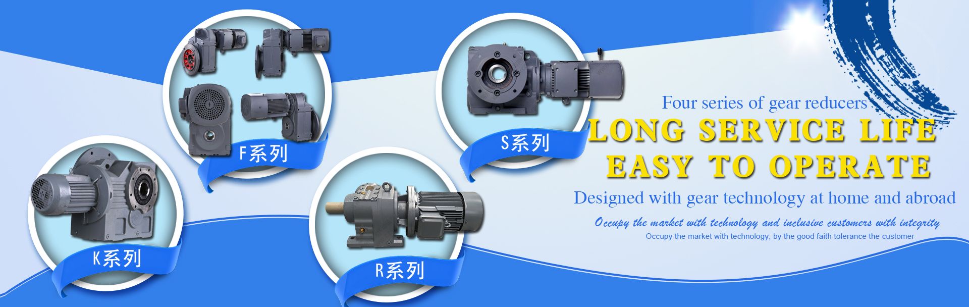
世界一流的齿轮制造能力、优质的材料供应商和最先进的质量工艺,使 EPT 能够提供最高水平的精度、耐用性和耐久性。EPT 行星减速器专为先进的高速、低背隙应用而设计和制造。EPT 的制造工艺使我们能够提供卓越的冲击载荷能力和各种安装选项。
表面处理

退火、自然钝化、热处理、抛光、镀镍、镀铬、镀锌、黄钝化、金钝化、缎面、黑色表面喷漆等。

处理方法

数控加工、冲、车、铣、钻、磨、拉削、焊接和装配

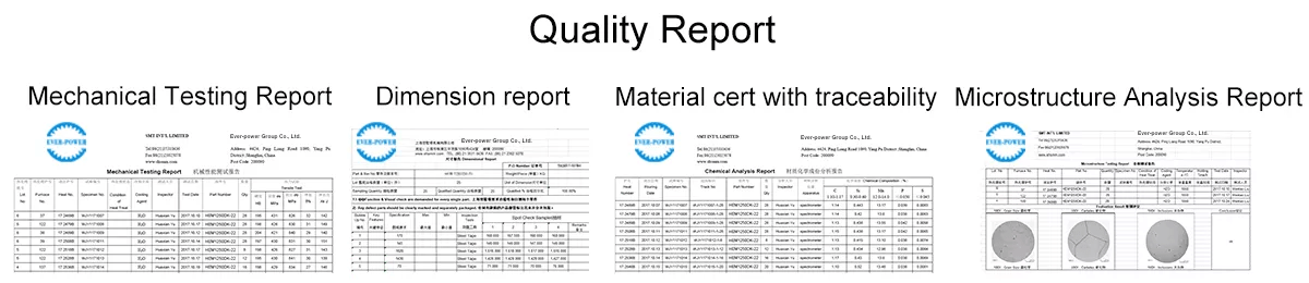
质量控制和证书

生产过程中由技术人员自检,包装前由专业质检员终检
ISO9001:2008 , ISO14001:2001,ISO/TS 16949:2009

包装和交货时间

尺寸图纸
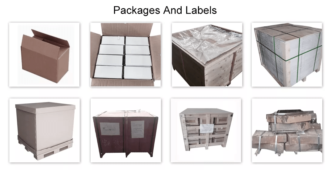
木箱/容器和托盘,或根据客户定制的规格。
样品 15-25 天。正式订单 30-45 天
港口:上海/宁波港
常见问题

问:你们是贸易公司还是制造商?
答:我们集团由 3 家工厂和 2 家海外销售公司组成。

问:你们提供样品吗?
答:是的,我们可以免费提供样品,但不支付运费。

问:你们的交货期有多长?付款条件是什么?
答:一般为 40-45 天。时间可能因产品和定制程度而异。对于标准产品,付款方式为30% T/T 预付,余款在发货前付清。

问:贵公司产品的具体 MOQ 或价格是多少?
答:作为一家 OEM 公司,我们可以根据广泛的需求提供和调整我们的产品。因此,MOQ 和价格可能会因尺寸、材料和其他规格的不同而有很大差异;例如,成本较高的产品或标准产品的 MOQ 通常较低。请联系我们并提供所有相关详细信息,以获得最准确的报价。

zh_CNZH